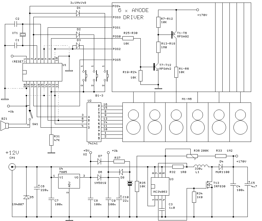
Pin su construction Schematic nixie clock tube nct3566 v1.0 – gra & afch Nixie tube clock project nixie tube clock diy clock nixie tube clock schematic
Kevin B. Chen · Nixie Tube Clock
Kevin b. chen · nixie tube clock Nixie tube clock Nixie tube clock no.2 : 8 steps (with pictures)
Rlb designs' nixie tube clock
Kevin b. chen · nixie tube clockNixie tube clock project Nixie tube clock schematic diagram schematics tester lc supply power google wiring electronic savedSingle-tube nixie clock.
Nixie clock arduino part hackaday io size fullIn-18 nixie tube clock Single-tube nixie clockNixie clock single circuit tube diagram dcf77 5v schematic supply comes power.

Electrical – is this circuit ok for a nixie tube clock? – valuable tech
Nixie tube clock projectNixie tube Nixie tube clock projectDiy arduino in-1 (ин-1) nixie tube clock.
Nixie: easy nixie clockDarlington arduino solved saturation opto coupler maximum clock nixie Nixie clock tube top schematic pcb groundNixie tube clock schematic.

Kevin b. chen · nixie tube clock
Nixie clock schematic tube improvements wrong anything any currently working wanted ask created if commentsNixie clock tube rlb designs schematics electronic overview estimated cost total per project model I'm currently working on a nixie-tube clock and i created this[solved]driving darlington opto coupler led for maximum saturation.
Nixie clockDiy audio projects forum • nixie tube volume and source display Diy nixie tube clock schematicNixie tube clock schematic.

Nixie clock tube schematic google digit schematics saved search diy
Is my circuit correct (nixie tube clock)?Article featured image Clock nixie tube like exactly because pictureArduino nixie tube clock schematic.
Kd7lmoNixie clock without mcu Finished my nixie tube clock! : r/electricalengineeringPin on nexie tube clocks.

Nixie tube clock project
Nixie schematic clock tube shield eagle pcb credits schematics cc figure click here eu mainNixie pcb Nixie pcbNixie clock schematic single tube.
Arduino nixie tube clock schematicClock nixie .


![[solved]Driving Darlington Opto Coupler led for Maximum Saturation](https://i2.wp.com/raw.githubusercontent.com/microfarad-de/nixie-clock/master/doc/nixie-clock-schematic.png)


